Ich habe mir kürzlich ein paar LED-Spots zugelegt. Diese wollte ich natürlich auch irgendwie steuern. So kam es, dass ich dazu auch noch ein USB-DMX-Interface nebst Adapterkabel kaufte und begann mich mit QLC+ zu beschäftigen.
QLC+ ist eine OpenSource-Software zur Lichtsteuerung mittels DMX512 und anderen Protokollen.
Beim Spielen mit QLC+ stieß ich dann auf ein Video vom Hauptentwickler, wo zu sehen ist, wie man mit QLC+ eine LED-Matrix ansteuert. Und da dachte ich: Das will ich auch!
Die LED-MatrixIch schaute also, wo man günstig an LED-Streifen (Stripes) mit Einzelpunktansteuerung kommt. Bei eBay wurde ich fündig; es gibt im Wesentlichen Streifen mit 4 verschiedenen Chips:
- WS8201
- WS8211
- WS8212
- WS8212B
Der WS8201 kommuniziert per SPI. Wie man diesen Stripe mit einem Raspberry ansteuert, findet man hier beschrieben. Diese Art der Ansteuerung wurde auch vom QLC+-Entwickler Massimo Callegari verwendet.
Ich entschied mich aus Kostengründen für drei mal 5 m Stripe mit WS8211. Das sind 900 LEDs; ich wollte eine Matrix von 75x12 Pixeln bauen. Die Stripes kamen gleich am nächsten Tag, ich suchte eine passende Holztafel und klebte die Streifen parallel darauf.
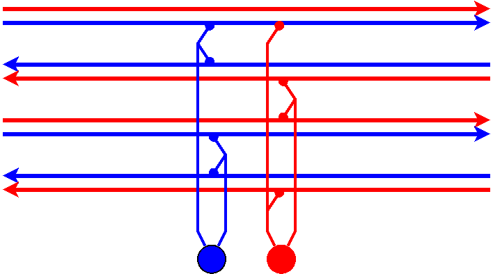
Stromversorgung & VerkabelungAuch wenn eine einzelne LED nicht viel Energie benötigt, so muss man doch sagen: Die Masse machts. 900 LEDs × 20 mA ergeben halt auch 18 A, oder – bei 12 V Betriebsspannung – 216 W. Deshalb war wichtig, dass jeder der 12 Stripes mit Strom versorgt wird und das Netzteil genug Leistung bringt. Ich hatte in einer Bastelbox noch ein altes Server-Netzteil und machte mich an die Verkabelung:
Da benachbarte Streifen gegenläufig sind, lagen jeweils gleiche Pole nebeneinander. Es bot sich also an, je zwei Streifen mit je einem Kabel für Plus und Minus an die Stromversorgung anzubinden:

Bei dem Netzteil handelt es sich um ein ATX-Netzteil, man muss am großen Stecker die grüne Leitung mit einer Masseleitung (schwarz) verbinden, um es einzuschalten.
Die Datenleitung ist einfach zu verkabeln: man muss nur den Pfeilen folgend die mittleren Pole des Stripes verbinden.
Auf den Bildern ist zu sehen, dass ich bei manchen Stripes auch die Stromleitungen verbunden habe. Dies hatte ich angefangen, bevor ich über die Stromversorgung nachdachte und ist nicht notwendig.
AnsteuerungFür einen ersten Test wollte ich meinen schon vorhandenen Raspberry Pi bemühen. Eine kurze Suche im Internet lieferte ein kleines Python-Programm, was genau für meinen Zweck zugeschnitten war:
WS2812 RGB LED Streifen per Raspberry Pi steuern¹.
Vorbereitungen
Dieser Anleitung folgend verband ich die Masse (Pin 6) des Raspberry mit dem Minuspol der LED-Stripes und Pin 12 (GPIO 18) mit der Datenleitung des ersten Stripes.
Dann folgende Schritte auf dem Raspberry:
sudo apt-get update
sudo apt-get install gcc make build-essential python-dev git scons swig
sudo echo "blacklist snd_bcm2835" > /etc/modprobe.d/snd-blacklist.conf
sudo nano /boot/config.txt
um die Zeile dtparam=audio=on nach #dtparam=audio=on zu ändern.
Dann neu starten und weiter:
Software-Installation
git clone https://github.com/jgarff/rpi_ws281x
cd rpi_ws281x/
sudo scons
cd python
sudo python setup.py build
sudo python setup.py install
Test-Script zur Steuerung mit python
Ich habe gemäß Anleitung einen Editor mit sudo nano examples/strandtest.py gestartet und die Zeile
LED_COUNT = 16 # Number of LED pixels. angepasst – ich habe ja 900 Pixel.
Dann habe ich nochmal geprüft, dass der richtige Pin für die Daten konfiguriert ist:
LED_PIN = 18 # GPIO pin connected to the pixels (18 uses PWM!).
Schon konnte das Ganze getestet werden:
sudo PYTHONPATH=".:build/lib.linux-armv7l-2.7" python examples/strandtest.py
Und es begann zu leuchten! Dabei fiel mir auf, dass ich etwas übersehen hatte: Bei den von mir gekauften Stripes werden immer drei RGB-LEDs gemeinsam von einem Controller gesteuert; ich habe also effektiv nur 300 Pixel, die jeweils drei LEDs breit sind. Dammit!
„Na gut“ dachte ich mir, dann hat die Matrix halt nur 25x12 Pixel. Auch gut.
Also die eine Zeile nochmals angepasst: LED_COUNT = 300 # Number of LED pixels.
Fertig.
Ansteuerung mittels QLC+
Das eigentliche Ziel war ja, die Matrix mit QLC+ verwenden zu können. Es war bekannt, dass dieses auf dem Raspberry lauffähig ist und dort per SPI Stripes mit dem WS8201-Chip steuern kann. Für meine WS8211-Stripes musste ich eine Lösung finden.
Hierfür hatte ich verschiedene Ansätze:
- SPI-Signal elektronisch konvertieren. Dazu fand ich zwei Schaltungen:
- SPI nach WS2811-Umsetzer mittels Standard-Logik
- WS2811 SPI Driver Using One Transistor And Passives
Ich habe beides nicht versucht, da ich eine andere Lösung fand (siehe unten).
- SPI-Signal programmatisch umsetzen
Hier war meine Idee einen Arduino als SPI-Slave zu benutzen, um die SPI-Signale zu empfangen und dann per Bit-Banging die LEDs zu steuern. Leider habe ich diesen Weg nicht hinbekommen; irgendwie hat der Arduino bei mir immer das erste Bit verschlafen. Außerdem ist die Taktrate des SPI-Signals zu groß. - SPI softwareseitig umsetzen
Die Idee hierbei wäre gewesen, QLC+ einen SPI-Port softwaremäßig vorzugaukeln, die Daten aber direkt im richtigen Format auszugeben. Ich hatte aber keinen Plan, wie dies zu implementieren sei.
Das alles wurde verworfen, als mir eine flexiblere Lösung einfiel:
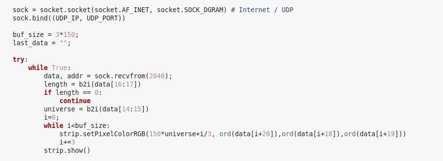
Man kann mit Python problemlos ArtNet-Signale empfangen und mit einer modifizierten Version des strandtest.py-Programmes die Matrix steuern!
 Das resultierende Python-Script kann dann einfach aufgerufen werden:
cd ~
sudo PYTHONPATH="rpi_ws281x/python/build/lib.linux-armv7l-2.7/" python artnet.py --brightness=255 -c
Dabei ist der Pfad rpi_ws281x/python/build/lib.linux-armv7l-2.7/ durch das entsprechende Verzeichnis (siehe → Software-Installation) zu ersetzen.
Das Script ist auf meine Hardware zugeschnitten: Die LED-Matrix ist in QLC+ auf zwei Universen mit je 150 RGB-Spots verteilt, die als Art-Net-Universen 0 und 1 über das LAN bespielt werden.
Das Script empfängt entsprechend nur Daten aus diesen Universen und schreibt für Universum 0 auf die LEDs 1-150 und für Universum 1 auf die LEDs 151-300.
Für andere Hardware muss das Script entsprechend angepasst werden.
PerformanceMein erster Aufbau nutzte einen Raspberry Pi Model 1. Hier musste ich leider feststellen, dass dieser zu langsam ist, um die Signale vom QLC+ in Echtzeit umzusetzen. Ich habe daraufhin das Ganze auf einem Raspberry Pi 3 eingerichtet. Und was soll ich sagen: es flutscht!
1) WS2811, WS2812 und WS2812B sind kompatibel. Es handelt sich um verschiedene Bauformen mit dem gleichen Controller

Neuen Kommentar hinzufügen